Project details
Maersk Offshore Wind (MOW) is involved in a new heavy lift jack-up vessel, which presents a challenge for structural strength checks via the loading computer. Unlike most other vessels, this one cannot be considered a slender structure, meaning its strength is determined by both transverse and longitudinal structures. Currently, most vendors’ loading computers focus only on longitudinal strength (1D-beam analysis), which is not sufficient for this vessel’s unique design. Some vendors have suggested using the same principles to check transverse strength, but this method does not account for the positioning of loads (starboard/port or fore/aft).
Client
Maersk Offshore Wind
Category
Loading Computer
Year
2025
Disciplines
Structure
Contact person

Steen Tange Hasholt
Our approach
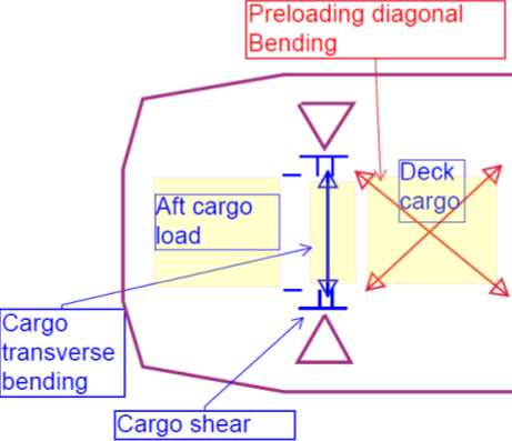
OSK staff studied the global hull girder analysis for the vessel and have proposed the approach illustrated on the left.
Bending stresses amidship are predominantly due to preloading conditions. Cargo aft, and deck cargo predominantly results in transverse bending in between the aft legs and shear stresses in parts of the longitudinal and transverse bulkheads adjacent to the aft legs.
Proposed 1D-Beam Analysis
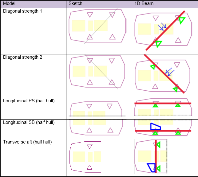
From these observations, it is recommended to create five separate 1D-beam analyses in the loading computer. When the strength criteria are met in all five 1D-beams, the structural check is considered passed.
Preloading Loads: Indicated on "Diagonal Strength 1 & 2."
Crane Loads: Indicated on "Longitudinal SB" and "Transverse Aft."
Notably, significant stresses are not observed in the forward part of the hull, which has been omitted from the structural verification. However, it can be included later as a sixth 1D-beam if necessary.

Bending Moment and Shear Force
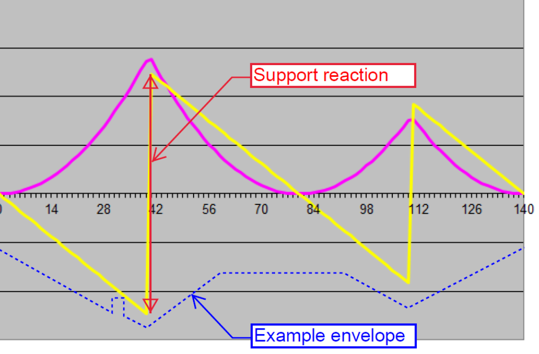
For the 1D beams, the analysis of bending moment and shear force is shown as illustrated.
It is expected that the shear stresses in the bulkheads adjacent to the legs will be proportional to the support reaction at the leg, as determined by the 1D-beam analysis. To determine if the hull girder strength is sufficient, allowable envelopes for bending moment and shear force must be developed.

Additional envelopes can be added if detailed analyses show this necessary.

Developing the 1D-Beam Models
To develop the 1D-beam models, lightship weight distributions that match the respective models must be derived. The 1D-beam models will be loaded using the same loading conditions analyzed in global hull girder FE-analyses. If the loading condition is just acceptable in the FE-analyses, then the corresponding bending moment and shear force curves become the allowable envelopes in the 1D-beam model. If the FE-analyses show results below acceptable stress limits, the loading will be increased until the maximum is reached, and those values will become the allowable envelopes.
The final allowable envelope will be the combined minimum of all loading conditions.
Monitoring Stress Distribution with 1D-Beams
The proposed 1D-beams can be thought of as "strain gauges" within the hull, where the governing stresses are observed in the global FE-model. These beams are "calibrated" by applying the same loads to both the 1D-beam models and the global FE-models. Each 1D-beam monitors different directions of the load distribution, and specific load distributions can be critical for some 1D-beams but not others. For a loading condition to be acceptable, all 1D-beams must be within their respective allowable envelopes.
The result
This multidirectional structural strength verification method for the vessel’s loading computer offers several advantages:
- Generic Method: Any combination of tank fillings, deck loads, crane loads, etc., can be tested.
- Familiar Principles: Vendors already use the 1D-beam approach for longitudinal strength verification.
- Operational Consistency: The crew will operate the loading computer based on principles already familiar to them.
- Conservative Results: Since the half-models do not account for load sharing between the hull parts, there will be a margin between the provided allowable envelopes and the actual hull capacity.